Components
Components of a Hydraulic System
Learning Objectives:
- Explain the application of hydraulics in fluid power systems.
- Explain the operating principles of hydraulics systems.
- Identify the components of hydraulics systems along with their functions.
- Compare hydraulic, pneumatic, electrical and mechanical systems.
Following are some basic components of a hydraulic system.
Pump:
A pump connected to an electric motor or a diesel generator is prime mover for hydraulic circuit. Pump can be positive displacement type such as piston type, internal/ external gear pump or rotary type such as centrifugal pump. Mechanical power is converted into hydraulic power by the pump. The pump is required to move the fluid within the system.
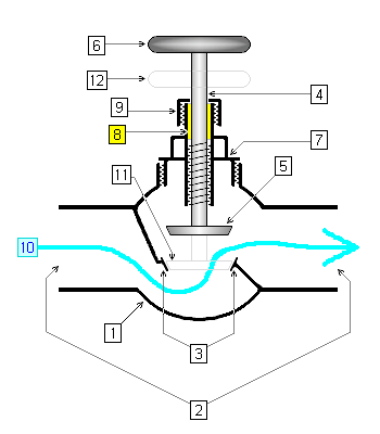
Flow Regulator:
A flow regulator or a flow control valve regulates the flow or pressure of a fluid.
Hydraulic Actuator:
Hydraulic power is converted to mechanical power by the actuator or piston. The actuator moves the fluid within the circuit to the work. The pressure of the fluid pushes up on the piston within the cylinder to lift the weight. A hydraulic actuator consists of a cylinder or fluid motor that uses hydraulic power to facilitate mechanical operation. The mechanical motion gives an output in terms of linear, rotary or oscillatory motion. Because liquid cannot be compressed, a hydraulic actuator can exert considerable force, but is limited in acceleration and speed.
Reservoir or Tank:
An area within the system that holds the hydraulic fluid. As the pump works to produce mechanical power, a supply of additional fluid is needed. The system receives this extra fluid from the reservoir.
Hydraulic pipes (or conductors):
Hydraulic power is transmitted by the fluid that is contained within the pipes.
Valves:
Hydraulic power is regulated by valves. The valves determine whether the piston rod is extending or retracting.
Solved Example: 100-1-01
A double acting cylinder:
A. Has two pistons
B. Has ports on both sides of the piston
C. Has double the acting pressure
D. Has twice the area available at the valve
A double acting cylinder can accept compressed fluid from both sides of the piston as it has ports on both sides of piston.
Correct Answer: B
Solved Example: 100-1-02
A solid (shaded) arrow or triangle in the Fluid Mechanics circuits or component symbols indicates:
A. This is direction of hydraulic fluid flow
B. This is direction of Pneumatic fluid flow
C. Air is conditioned before it goes to the remaining circuit
D. The component is operated by push button.
In Fluid Mechanics symbols, an empty triangle represents pneumatic direction of flow(air) whereas a solid filled black triangle represents hydraulic direction of flow (oil).
Correct Answer: A
Solved Example: 100-1-03
Hydraulic and pneumatic systems are common components of what land transportation component?
A. Brakes
B. Acceleration systems
C. Docking systems
D. Instrumentation
Correct Answer: A
Solved Example: 100-1-04
A hydraulic accumulator normally consists of:
A. Two cylinders, two rams and a storage device
B. A cylinder and a ram
C. Two co-axial rams and two cylinders
D. A cylinder, a piston, storage tank and control valve
A hydraulic accumulator is a pressure storage reservoir in which a non-compressible hydraulic fluid is held under pressure that is applied by an external source. The external source can be a spring, a raised weight, or a compressed gas. An accumulator enables a hydraulic system to cope with extremes of demand using a less powerful pump, to respond more quickly to a temporary demand, and to smooth out pulsations. It is a type of energy storage device. Source: Wikipedia
Correct Answer: B
Solved Example: 100-1-05
A hydraulic intensifier normally consists of:
A. Two cylinders, two rams and a storage device
B. A cylinder and a ram
C. Two co-axial rams and two cylinders
D. A cylinder, a piston, storage tank and control valve
Correct Answer: C
Solved Example: 100-1-06
Hydraulic accumulator is used for:
A. Accumulating oil
B. Supplying large quantities of oil for very short duration
C. Generally high pressures to operate hydraulic machines
D. Supplying energy when main supply fails
Correct Answer: D
Solved Example: 100-1-07
Higher viscosity in a hydraulic system will cause which of the following?
A. Increased friction due to difficulty in pumping
B. Reduced effectiveness due to inability to stick to surface
C. Foaming possibility especially at lower temperatures
D. Reduced corrosion resistance.
Correct Answer: A
Solved Example: 100-1-08
Lower viscosity in a hydraulic system will cause which of the following?
A. Increased friction due to difficulty in pumping
B. Reduced effectiveness due to inability to stick to surface
C. Foaming possibility especially at lower temperatures
D. Reduced corrosion resistance.
Correct Answer: B
Components of a Pneumatic System
Learning Objectives:
- Explain the meaning of Pneumatics.
- Explain the operating principles of pneumatic systems.
- Describe components of a pneumatic system with their symbols and functions.
- Describe basic construction of air preparation system such as filter, regulator and lubricators.
- State the necessity of end position cushioning in case of pneumatic cylinders.
- Identify and appreciate the application of pneumatic systems in various Industries.
- The Reservoir stores potential energy in the form of compressed air.
- The Shut Off/Purge Valve isolates the stored air from the working components in the pneumatic circuit. This valve depressurizes or vents the circuit when it is closed.
- Regulator maintains a set pressure in the circuit.
- Solenoid electronically controls the flow of air to the pneumatic cylinder.
- Pneumatic Cylinder converts the pressurized air into the mechanical energy of a linear rod and piston.
Single and Double Acting Cylinders:
Single acting cylinder has one working port. Forward motion of the piston is accomplished to due to supply of compressed air behind the piston. Return motion of piston takes place only due to built in reset spring placed on the rod side of the cylinder. Single acting cylinders are used for applications such as clamping, feeding, sorting, locking, ejecting, braking etc., where force is required to be exerted only in one direction.
Double Acting Cylinders are equipped with two working ports- one on the piston side and the other on the rod side.
To achieve forward motion of the cylinder, compressed air is admitted on the piston side and the rod side is connected to exhaust. During return motion supply air admitted at the rod side while the piston side volume is connected to the exhaust. Force is exerted by the piston both during forward and return motion of cylinder
End Position Cushioning:
Pneumatic cylinders operates at much higher speeds than Hydraulic cylinders. Due to this, there is a tendency of the piston to ram against the end covers as the piston approaches the ends at high velocity especially in cylinder with large mass. This impact force can damage the cylinder as well as the piston due to repetitive action. All Double acting cylinders excepting for small sizes, are provided with end position cushioning arrangement.
Compressed Air Receiver:
Compressed Air Receiver, which can be horizontal or Vertical, depending on available floor space, are used to stored compressed air. Air receivers should be equipped with delivery line, Safety valve, Drain cock, Pressure gauge.
Compressed Air Filter:
In compressed air filter, dust and moisture are arrested outside the filter element as the air flows from out side to inside. This is periodically drained with the help of manual drain cock. or automatic drain arrangement.
Compressed Air Regulator:
The Compressed Air Regulator maintains constant down stream pressure in the air line, irrespective of variation of upstream pressure.
Compressed Air Lubricator:
Lubrication of moving parts of cylinder and valves is very essential in Pneumatic system For this purpose Compressed Air Lubricators are used ahead of each Pneumatic equipment.
Low pressure is created at the throat portion of the venturi due to flow of air taking place in the Lubricator. This low pressure will assist automatic suction of the lubricating oil from the oil bowl to the drip chamber where drop by drop of oil is diffused in to air stream.
Solved Example: 100-2-01
The centrifugal air compressor:
A. Has valves that open and close at the proper time
B. Uses a series of rotors equipped with blades
C. Is only made in a single stage design
D. Uses an impeller to impart radial momentum to the air
A reciprocating compressor has inlet and outlet valves which close at proper time.
A centrifugal compressor can be multistage.
A centrifugal compressor uses impeller or more accurately, rotating vanes, instead of a reciprocating piston, to impart radial momentum to the air.
Correct Answer: D
Solved Example: 100-2-02
In an air compressor system, the _________ is also called the receiver.
A. Intake filter or silencer
B. Compressor
C. Storage tank
D. After cooler
The Receiver stores potential energy in the form of compressed air, thereby acting as a storage device.
Correct Answer: C
Solved Example: 100-2-03
In a two-stage compressor, the inter cooler:
A. Pre-cools the air entering the first stage compressor
B. Removes the heat of compression from air leaving the first stage
C. Cools the air leaving the second stage compressor
D. Cools the cylinders when running under a heavy load.
The intercooler, as the name suggests, is in between the stages of a two stage compressor. When the air exits from first stage it is hot due to compression process. Intercooler reduces the volume by removing the heat (thereby increasing the density) before the air goes into the second stage of compression.
Correct Answer: B
Solved Example: 100-2-04
In pneumatic systems, the following components are mostly together as a unit:
A. Throttle valve and direction control valve
B. Compressor and double acting cylinder
C. Filter, Regulator and Lubricator
D. Air receiver and distributor
Let us see the options individually.
In one way flow control valve, there is throttle valve and check valve, which is connected in parallel.
Compressor and double acting cylinder can be independent. Moreover, it is not necessary that only double acting cylinder has to be used. A single acting cylinder can also be used based on the requirements, especially when forces are required only in one direction.
Filter, Regulator and Lubricator are often together at the beginning of a pneumatic circuit, just after compressor and air receiver, and before distributor and direction control valve.
Air receiver and distributor both are often required, but they are not necessarily together as a unit.
Correct Answer: C
Solved Example: 100-2-05
A tube has the following advantage over pipe:
A. Lighter and easier to handle
B. Greater shock absorption
C. Smoother inside walls
D. All of the above
Pneumatic system are used when less forces are required compared to hydraulic system. Pneumatic systems use tubes, which are lightweight, easy to handle, flexible and hence absorb shocks due to sudden closure and opening of valves. They have smoother inside walls. Hydraulic systems use pipe where leakage problems are more of a concern. The end connectors are metallic for perfect connections, which is more reason why hydraulic systems used pipes rather than tubes.
Correct Answer: D
Solved Example: 100-2-06
The study of pneumatics deals with system operated with:
A. Oil
B. Solid
C. Water
D. Air
Correct Answer: D
Valves
Learning Objectives:
- Define the function of a Direction Control Valve (DCV).
- Able to name DCV as per standard naming procedure.
- Explain the various types of DCV.
- Explain the various methods of valve actuation.
Flow Control Valves:
H Padleckas, CC BY-SA 3.0, via Wikimedia Commons
Directional Control valves:
Directional Control valves are mainly used to change the direction of flow path of working medium or signal medium. They are used for admitting or exhausting working medium to the cylinder or from the cylinder for actuation of the cylinder. Also used to start or stop the pneumatic signal as well as for signal processing.
A 3/2 Roller Operated Direction Control Valve
A 5/3 valve has one input, two outputs and two vents (total 5 ports). It is activated by air signal input known as pilot)
Directional control valves are designated as per the following functions:
- Number of ports on the valves
- Number of switching positions
- Method of actuation
- Method of reset
- Design and constructional features
Logic Control Valves
Logic Control Valves allow or block flow based on OR or AND logic. A shuttle valve operates based on OR logic (means allows flow if first OR second input is high) whereas a two-pressure valve operates based on AND logic (means allows flow if first AND second input is high).
A Shuttle Valve
A unidirectional flow control valve allows control of flow in one direction, but in the other direction allows quick return.
Solved Example: 100-3-01
A 5/3 pneumatic direction control valve will have:
A. 5 vents
B. 3 vents
C. 2 vents
D. 1 vent
Please see the symbol of a 5/3 DCV.
Correct Answer: C
Solved Example: 100-3-02
In a pneumatic system, an AND gate is known as:
A. Non return valve
B. Gate valve
C. Check valve
D. Dual-pressure valve
Correct Answer: D
Solved Example: 100-3-03
Overlapping of signals in pneumatic systems can be avoided by using a/an:
A. Rolling lever valve
B. Idle roller
C. Lever valve
D. Roller
Correct Answer: A
Solved Example: 100-3-04
An OR logic control in pneumatic systems is possible with the help of:
A. Sequence valve
B. Shuttle valve
C. Dual pressure valve
D. Delay valve
Correct Answer: B
Solved Example: 100-3-05
Which of the following valves is used to prevent product flow in a wrong direction?
A. Seat valve
B. Half turn valve
C. Check valve
D. Butterfly valve
Correct Answer: C
Electromechanical Components
Learning Objectives:
- Know different types of switches.
- Identify and list the different parts of a relay.
- List applications of relay.
- State the main function of a circuit breaker.
- Understand the difference between a circuit breaker and a fuse.
Switches:
In electrical and electronic system, a switch is a device, which can make or break an electrical circuit or we can say that switch is a controlling device, which interrupt the flow of current or direct the flow of current in another direction. Almost all the electrical and electronics systems contain at least one switch, which is used to make the device ON or OFF. In addition, a switch is used to control the circuit operation and user may able to activate or deactivate the whole or certain parts of the connected circuit. Generally, Switches can be categories as:
- Mechanical Switches
- Electrical/Electronic Switches
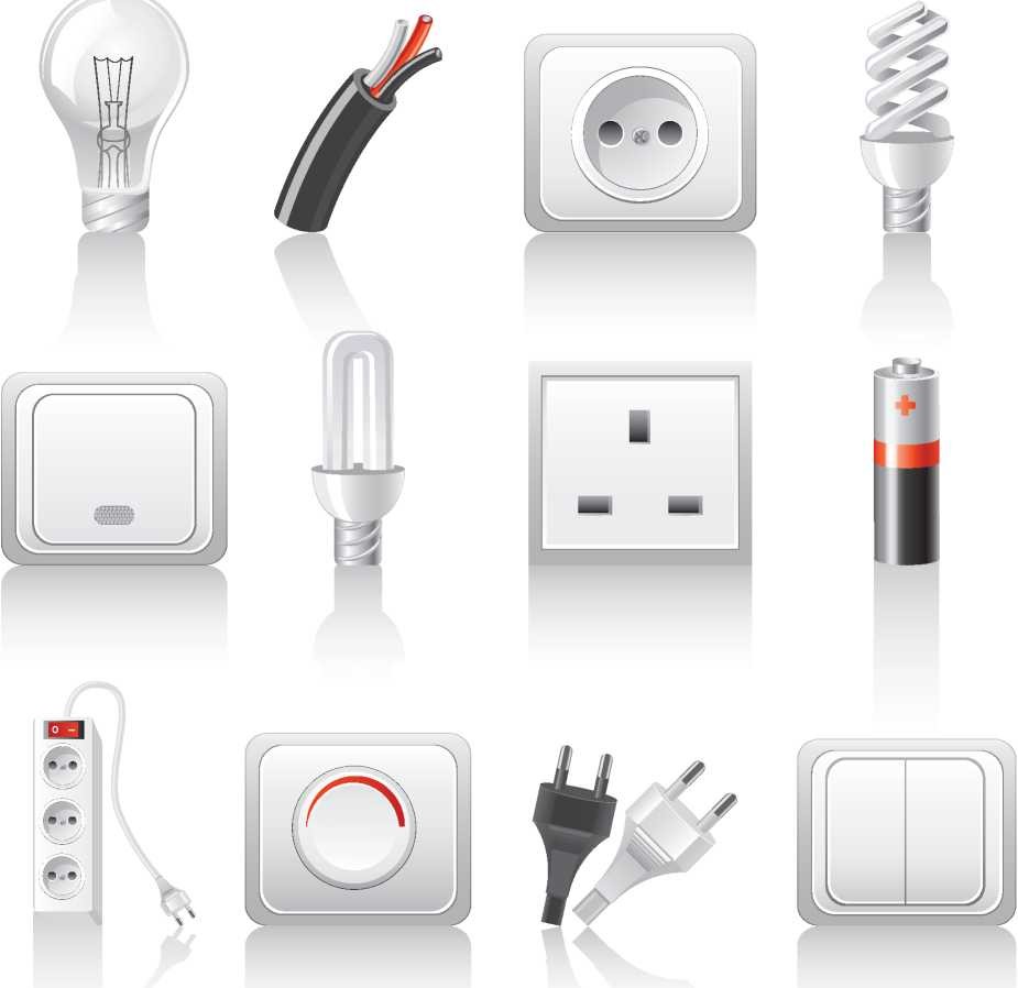
Electrical Components
Zuhriddin Ma'ruf, CC BY-SA 4.0, via Wikimedia Commons
Mechanical Switches:
Mechanical switch is a switch in which two metal plates touch each other to make a physical contact for the current to flow and separate from each other to interrupt the flow of current. There are many types of Mechanical switches and they are also be categories on the basis of power handling capacity. The contact material is chosen by keeping in mind that the metal oxides, which produced due to corrosion, are mostly insulator and layers of such oxides on the switch plates will hinder the normal operation of the switch.
Depending upon the types there are four different types of Mechanical switches:
- SPST = Single Pole, Single Throw This is a simple ON/OFF switch. It is also called as One Way Switch (in the US, they called it Two-Way Switch). When a user press the button of the switch, then the plates of the switch connect with each other and the current starts to flow and vice versa.
- DPST = Double Pole, Single Throw This switch is basically two SPST switches in one package and can be operated by a single lever. This switch is mostly used, where we have to break both ground and lines at the same time.
- SPDT = Single Pole, Double Throw This button has three pins in which, one pin is used as common and called a Two-Way Switch (in US, they called it Three-Way Switch). We can send two different signals to same pin by using this switch. Because of this functionality, this switch is also called selector switch. Other switches related to SPDT are SPCO (Single Pole Changeover) and SPTT (Single Pole Center Off or Single Pole Triple Throw)
- DPDT = Double Pole, Double Throw: This switch is equivalent to two SPDT switches packaged in one pack. This switch has two common pins and four signal pins. Total four different combination of singles can be applied to the input pins of this switch. Another switch, related to DPDT is DPCO (Double Pole Changeover or Double Pole, Centre Off).
Relays:
While a switch closes its contacts by the mechanical actuation of its lever, the relays do this by an electromagnetic coil pulling its contacts by the force of magnetism. A coil carries current and is wound over a core of soft magnet; the moving armature of the core causes the contact closure. In this way, by switching on the current through the coil of the relay, the relay contacts close. Relays can have several poles and several contacts. The contacts can be normally closed or normally open.
Terminology of a Relay:
- Electromagnet - a coil of wire wrapped around a conductive core.
- Armature -that can be attracted by the electromagnet
- Spring- to keep the armature in a ’home’ or ’normal’ position
- Control Circuit - connects to the coil of the electromagnet
- Secondary circuit usually a higher voltage and amperage demand than the control circuit.
- Coil -the wire wrapped around the conductive core of the electromagnet assembly.
Circuit Breakers:
All electric circuits needs a switching device and also a protective device. Switchgear is the general term covering a wide range of equipment connected with switching and protection. A circuit breaker is a switching and circuit interrupting device. A circuit breaker serves two purposes:
- Switching on and off during normal operation for maintenance etc.
- Switching during abnormal conditions- short circuits, earthing etc. to protect the associated equipment.
In short, a circuit breaker is a sort of automatic switch which can interrupt the fault currents.
Solved Example: 100-4-01
The function of protective relay in a circuit breaker is:
A. To ease any stray voltages
B. To close the contacts when the actuating quantity reaches a certain predetermined value
C. To limit arcing current during the operation of circuit breaker
D. To provide additional safety in the operation of circuit breaker.
Correct Answer: B
Solved Example: 100-4-02
A material best suited for manufacturing of fuse wire is:
A. Aluminium
B. Silver
C. Lead
D. Copper
Correct Answer: B
Solved Example: 100-4-03
A fuse is normally a:
A. Current limiting device
B. Voltage limiting device
C. Power limiting device
D. Power factor correcting device.
Correct Answer: A
Solved Example: 100-4-04
Most of the fuses operate due to _______ effect of current:
A. Heating
B. Magnetic
C. Electrostatic
D. None of the above.
Correct Answer: A
Solved Example: 100-4-05
A fuse wire should have _______ specific resistance and ______ melting point.
A. Low, high
B. Low, low
C. High, high
D. High, low
Correct Answer: D
Solved Example: 100-4-06
A circuit breaker is:
A. Power factor correcting device
B. A device to neutralize the effect of transients
C. A waveform correcting device
D. A current interrupting device
Correct Answer: D
Solved Example: 100-4-07
A circuit breaker will normally operate:
A. When the switch is put on
B. When the line is to be checked
C. When the power is to be supplied
D. Whenever fault in the line occurs.
Correct Answer: D